Test Socket & Fixtures industrial solution
Home/Solutions/Test Socket & Fixtures
06 / Precision contact. Repeatable test.

Semiconductor test sockets.
Precision at every contact.

THE MXPAC APPROACH

Test Socket & Fixtures

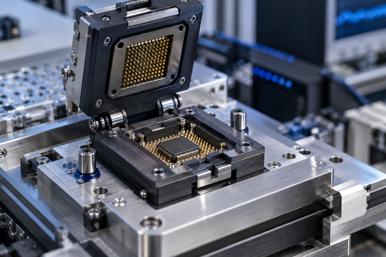
MXPAC provides semiconductor test socket and fixture engineering in Penang, Malaysia. We engineer the interface between device and tester—balancing contact, alignment, access, serviceability and production handling.

DESIGNED OUTCOMEA robust, serviceable test interface designed for consistent contact and production use.

TEST SOCKET SOLUTIONS

The contact technology
behind a reliable test.

Match the socket to the device package, electrical test and operating conditions. Our scope brings together contact selection, custom socket design, fabrication and integration with the mechanical and thermal test setup.

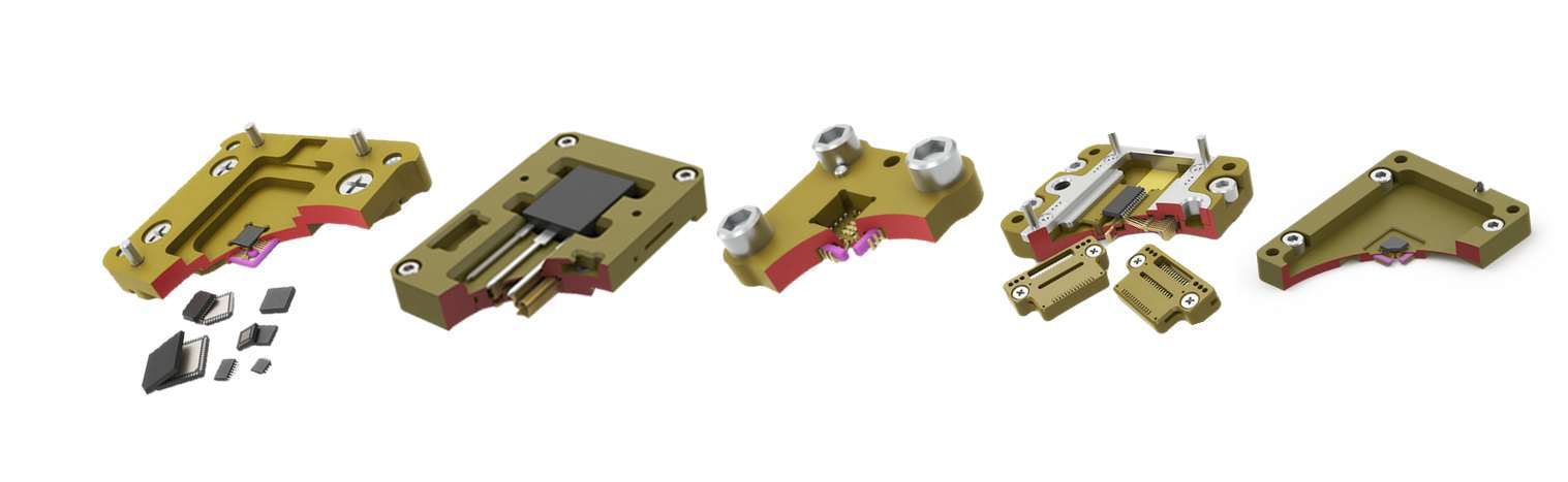
Range of semiconductor test socket assemblies and device packages from the supplied socket overview
Socket and contact configurations for different device packages and test arrangements.
01 / SELECTContact technology

Rubber, spring-probe, rigid-pin, cantilever and coaxial approaches.

02 / CUSTOMIZEPackage interface

Socket geometry, alignment, contact arrangement and fixture requirements.

03 / INTEGRATEComplete test setup

Load-board interfaces, mechanical support and thermal-system compatibility.

TECHNOLOGY OPTIONS

Choose around the test requirement.

Each contact family addresses a different combination of contact force, compliance, current and signal performance.

01 / RUBBER & ELASTOMER

Compliant contact
for sensitive devices.

Soft silicone-rubber contactors support semiconductor testing where ball or pad damage and contact force are important considerations. The supplied material includes BGA/LGA and memory applications, with fine-pitch and high-speed options.

Review for your application
Pitch, contact force, stroke, contact resistance and operating temperature.
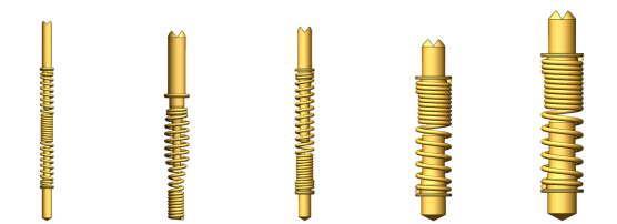
Spring probe contact pin examples with different tips and spring geometries
02 / SPRING PROBE

Contact compliance
across device interfaces.

Spring probes offer travel to accommodate package non-coplanarity. Options in the presentation include fine-pitch, Kelvin, RF, high-current and non-magnetic pins, with the contact geometry selected for the test environment.

Review for your application
Tip shape, travel, force, current, package flatness and maintenance access.
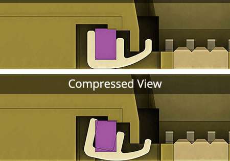
Cantilever contact mechanism shown in rest and compressed conditions in the supplied socket summary
03 / SHORT RIGID PIN & CANTILEVER

Contact structures for
demanding electrical tests.

The supplied presentation positions short rigid-pin sockets for 5G and other high-frequency applications, and cantilever sockets for automotive and high-power testing. Select the structure around the electrical path and loading requirements.

Review for your application
Signal path, current, contact arrangement, alignment and mechanical loading.
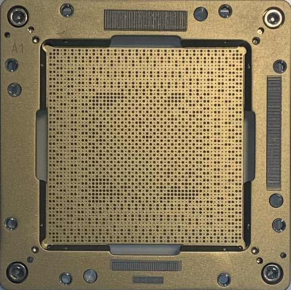
Coaxial test socket contact array from the supplied JF Technology presentation
04 / COAXIAL

Shielded signal paths
for high-frequency testing.

Coaxial socket structures use a metal housing and controlled contact geometry to address impedance and crosstalk. The presentation includes BGA and WLCSP examples, plus independent coaxial channels and differential-pair arrangements.

Review for your application
Pitch, test height, impedance, insertion loss, return loss and pin assignment.

Technology descriptions and selected images draw on the supplied JF Technology presentation. Product-family capabilities vary; the final socket configuration and performance are confirmed against your device and test requirements.

FROM SOCKET TO TEST STATION

Make the interfaces
work together.

A socket is one part of the test system. Define the board connection, device positioning, contact loading and thermal access together.

01

Test interface products

Review the load board, adaptor and fixture arrangement around the DUT and tester, including access for assembly and service.

02

Mechanical integration

Coordinate device guidance, clamping and support with the contact stroke and force needed for repeatable engagement.

03

Thermal integration

Plan thermal-head access and the socket’s operating range together for temperature-conditioned testing.

Explore Thermal Solutions →
START YOUR SOCKET REVIEW

Share the package.
Define the test.

Send the device drawing, package type and pin map, together with the operating conditions and tester interface.

  • Device & geometryPackage dimensions, pitch, ball or pad layout and pin count.
  • Electrical testSignal frequency, current, resistance targets and Kelvin requirements.
  • Mechanical & thermalContact force, stroke, test temperature, handling and fixture constraints.
  • Operation & supportTest cycles, cleaning method, service access and acceptance criteria.
WHEN THIS SOLUTION FITS

Start with the constraint,
not the equipment.

01

Intermittent contact or unstable test results

02

Device alignment and handling damage

03

Frequent socket maintenance or changeover

04

Fixture limitations during test automation

WHAT WE PROVIDE

A connected scope
from concept to support.

  1. Device and test-interface review
  2. Socket and contact concept
  3. Precision alignment and clamping
  4. Handler / fixture integration
  5. Maintenance access and replaceable wear parts
TYPICAL APPLICATIONS
Semiconductor package testPCB functional testCustom electrical fixtureBurn-in interfacePrototype validationAutomated test handling
SAMPLE USE CASES

See where the solution
fits into production.

These examples show deployment points, typical system components and the operating result. Final equipment selection follows the site, range, environment and interface study.

Example deployment for Test Socket & Fixtures
DEPLOYMENT VIEWDevice + process + controls + data
01

Semiconductor package test

WHEREBetween the DUT and tester load board

SYSTEMCustom socket, contactor, alignment nest, compression mechanism and PCB interface

FLOWLoad device → align → apply controlled force → test → release without damage

Maintains repeatable electrical contact through production cycles.
02

PCB functional fixture

WHEREAt bench test or an automated end-of-line tester

SYSTEMPogo-pin bed, guided clamping, connector interface, sensors and safety cover

FLOWLocate PCB → clamp → connect signals → execute test → display result

Turns a manual probe process into a controlled, serviceable test station.
03

Automated device handling

WHEREInside a handler, pick-and-place system or reliability station

SYSTEMSocket, nest, actuator, presence sensing and machine interface

FLOWRobot loads DUT → fixture confirms seating → test runs → DUT is sorted

Connects precision contact with automatic loading and result-based handling.
PROJECT FLOW
01Discover

Process observation, samples, constraints and success criteria.

02Engineer

Concept, risk review, controls and integration details.

03Validate

Build, testing and acceptance against the agreed intent.

04Deploy

Installation, training, handover and support planning.

START A CONVERSATION

Let’s review your
process challenge.

Tell us what the process needs to achieve. We will help define the practical engineering questions first.

Start a project ↗